How to install Press Counters for Barcode Inventory System
When installing press counters for Excel Software System Barcode Inventory, there are a few
things to consider. First, the magnet needs to be affixed to a place on a shaft or gear that always
moves when paper is moving through the press. The ideal scenario would be to choose a location
where one revolution would be equal to one impression. If this is not possible, we can rectify any
discrepancies using an internal software ratio adjustment.
It is Excel Software’s preference to not affix the magnet to a gear. We feel that just by the nature of
the hardware that it is safer to install the magnet on topside rather than gearside. In our
experience, we have found that mounting the magnet on the form liner punch shaft key works very
well. This technique allows us to install the magnet away from moving gears and to just mount an
L-bracket for the sensor off the gear side press wall. This eliminates most installation headaches
and keeps the sensor in an accessible location in the event that troubleshooting is ever required.
Excel Software recommends that the counter assemblies are installed on a press shaft that is an
EVEN number of inches round, and that does impressions at a ration of 1:1 to the cylinder the
sensor will be mounted to. If this cannot be accomplished, contact Excel Software for further
instructions.
When installing the magnet on multi-cylinder presses, the best case scenario is to pick a location
that feeds the same number of inches regardless of cylinder size. This will eliminate the need for a
pressman to have to check into a new cost center every time he changes cylinder sizes. It will also
save time when analyzing daily reports since all work done on a particular press will be confined to
a specific cost center.
To install a press counter:
1. Magnets: Under normal circumstances, magnets are not permanently installed (i.e. glued to
the shaft key) unless an Excel Software employee is present. Excel Software suggests that you
place the magnet on the shaft simply to determine how close to mount the sensor. Once this
has been determined, the magnet should be removed before the press begins running again. It
will not take very much time for an Excel Software representative to permanently install these
when he arrives for an on-site installation if everything else is already setup. The only reason
that we suggest this is because the magnet is not reusable if chipped or broken. If they are
glued in the wrong place, they will likely be destroyed when they are removed. In the absence
of an Excel Software on-site installation, careful consideration should be give regarding the
placement of the sensor magnet and the sensor and once decided upon, affix the sensor
magnet with super glue or epoxy to it’s permanent location. (Also see item 2. Sensors, below)
2. Sensors: After bringing the press to a complete stop, place the magnet on the shaft key as
described above. Find a place on the gear side press wall where you can mount an L-bracket.
Ultimately the sensor will be attached to this bracket. Hence, the bracket must be constructed
so that when the sensor is attached, it is no more than 1/8 inch away from the magnet. Usually,
we use flat bendable aluminum rods approximately 3/4 of an inch wide. These can be easily
obtained from any local hardware supply. Cut, bend, and mount your L-bracket. At this point,
insure that the face of the sensor will be located directly parallel to the black face of the magnet
and resides no further than 1/8 inch from the magnet itself when installed on the bracket. When
you feel comfortable that everything is constructed properly, you can attach the sensor to the L-
bracket. Excel Software suggests drilling a hole in the L-bracket and using the two nuts on the
sensor to attach the sensor to the L-bracket and set the gap. If a replacement is ever needed,
it is easier to replace the sensor if it is not glued to the bracket. After this is complete, jog the
press a few times to make sure that as the magnet rotates, it aligns with the mounted sensor.
When this is verified, remove the magnet and continue this process with the other presses.
(Also see item 1. Magnets, above).
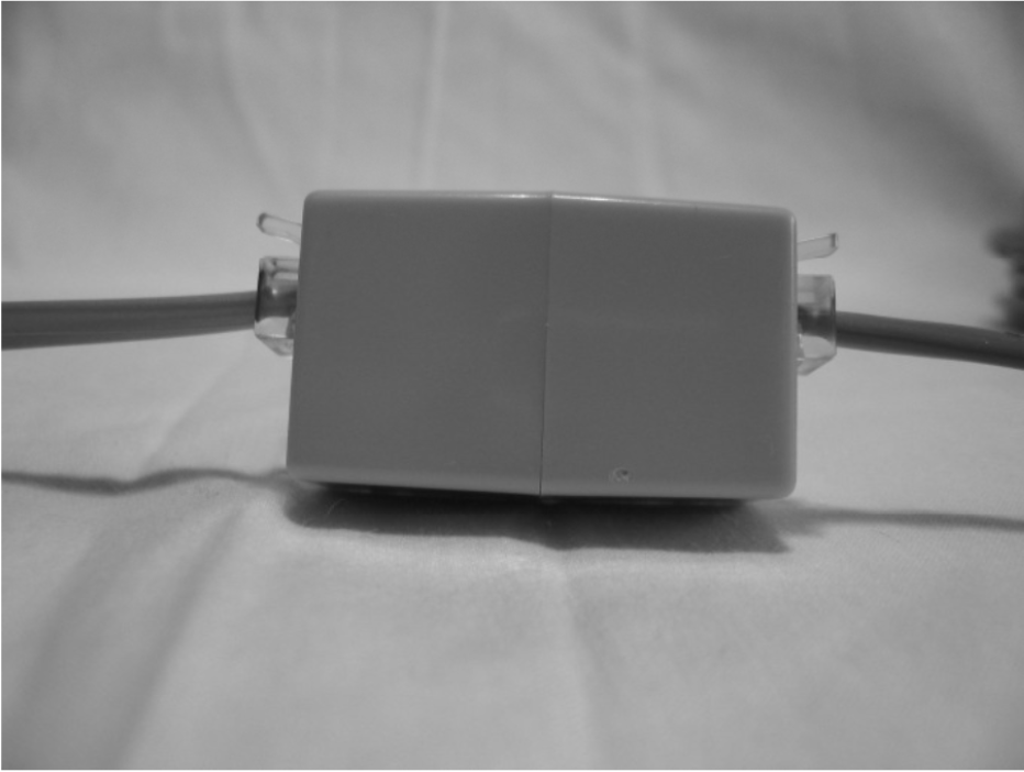
3. Cabling: For each counter assembly, a cable segment must ultimately be run between the
LabJack connected to the computer and the sensor mounted on the press which is coupled
together with an RJ11 inline coupler. The ideal situation is to run the cable through a conduit to
protect it. This is not mandatory of course but it could prevent the cable from possible damage
and save replacement time in the event the cable is ever severed. If you choose not to run the
cable through a conduit, we have a single suggestion. When draping the cable above the
press, it should be okay to have the cable cross light fixtures, but if at all possible do not run
the cable parallel to light fixtures. This has caused noise problems in the past. Even if using
shielded wire, we still discourage running the cable parallel to pressroom light fixtures. Then
just run a cable with ample length to reach from the sensor/coupler assembly to the LabJack
device connected to the computer.
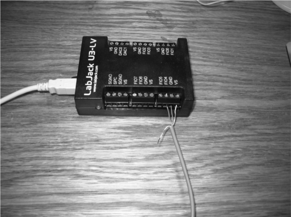
4. LabJack device: If installing the device to a computer for the first time, contact Excel Software
for assistance with the cable wiring.
Below are illustrations to help understand the flow of the hardware from the sensor magnet to the
PC card.
The series is as follows; magnet on gear aligns with sensor face, sensor connects to the RJ11
coupler, the coupler connects to one end of the counter cable, the other end of the counter cable
plugs into the PC card (installed in the computer).